
Alan Barnard
Port Angeles, WA
Flight duration is directly related to seat comfort! Or…"sore butt or what?"
As much as I love my Challenger II, it is not without a few
shortcomings, one of which is the seat! In my first Challenger, I had the canvass type
which shoved me forward and thus my knees in my chest. If I wanted that, I would own a J3.
I should say that I weigh about 250 lbs…not what Dave had in mind when he designed
the seat.
In my second and current Challenger, the seat had been replaced
with a solid aluminum plate, exactly like the "new" Challenger seat. With the
stock cushion and another 3" cushion under that, and my knees hiked up as guys like
me have to sit, my tail bone got sore in the first 20 minutes or so and I was shifting
around trying to stave off the need for an interim landing opportunity just to get out and
walk around.
Solution? The seat plate was about 17 inches long or so. I
removed it, cut it in half and reinstalled the approximately 8 ½ " section to the
front leaving a 8 " to 9" gap between the seat back and the shortened plate,
right where the tail bone sits.
I then drilled a few holes in the back edge of the shortened
plate. Lacking any web material or something more professional to make a "sling"
I took long wire ties and stretched them from the hole in the shortened seat plate and the
cross tube at the rear of the seat, leaving them long enough to slump with my tail bone a
couple inches or so. (see photo)
Now, the shortened plate supports my thighs which has plenty of
strength to hold me up under higher "G" maneuvers, and the "sling"
made of wire ties, allows my butt to have a nice little pocket to sit in. I added a seat
back cushion that I bought from a local auto parts store under the stock seat cushion to
slump into the pocket giving my butt plenty of cushion and not pressing the stock cushion
against the edge of the shortened plate thus cracking the vinyl. (see photo) Take care to
file the shortened plate edge down and I put a couple layers of gray fabric tape along the
edge to insure that the cushions were not cut by a sharp edge.
My flight durations are now only ruled by fuel capacity
and not comfort. Because I can sit lower and nestle into my little butt pocket, my legs
are allowed to be straightened out more, lowering the knees and making for generally much
enhanced comfort. I can honestly say that I have NO sore butt or tail bone problems at
all! I can fly two hours with perfect comfort.
If you want to get more professional, one could use webbing such
as the lawn chair type which could be riveted to the shortened plate and wrapped around
the back tube. For now, my wire ties work perfectly and flying my Challenger has no
comfort distractions.
This modification cost virtually nothing and took about an hour
to complete considering I already had the aluminum seat and back. If you have the canvass
seat, you will need to make up a seat back and half plate for seat, which will take you
longer. Either way, it is not an ordeal…but the payoff of well worth it! Ahhhhhh!
Because I have an ample posterior, I also made another
modification to the rudder pedals for the rear seat. I cut them off diagonally, rivited a
small tube along the edge so there was no sharp edge thus they no longer rub against my
legs. (See Photo)
Auxiliary Fuel Tank PHOTOS:
1. The aux. tank placed in airplane
2. A straight on shot of facet pump mounted
3. A side view of facet pump mount
4. The outlet valve and the 2X4 spacers glued to the bottom of tank to
protect the outlet valve.
5. How I drilled my tank cap and installed hose and quick disconnect.
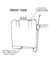
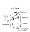
Jim Duke's diagrams with a little enhancement for clarity:


1. Front View
2. Side View
I basically followed Jim's layout. I added the 2X4's and the fuel
cap hose entry as my own ideas. Needless to say...so I'll say it..I neither
recommend nor endorse this approach to aux. fuel to anyone. It was my
choice to use it as it will be others and they should satisfy themselves with
regard to any and all issues connected with this approach. It is only what
I did.
It works really slick. My facet pump pumps 1/2 gallon a
minute. If you use a faster one, I think you will need to be sure that the
air will displace as fast as the fuel goes in.
582 Installation
My
design of Stabilizer Fins
I
have my second Challenger II, and fly frequently with the doors on.
In that configuration, I too have found that the yaw axis “wallows”
rather responds to my input. I felt I could live with it until I had a reason to practice
slips. Ugh! I decided then that I wanted more predictability and response
to the rudder with doors on and set about to solve the problem.
I
read an article in the ICOA newsletter describing stabilizer fins which sounded
interesting. I also reviewed the
recommended fins from Quad City. What
I did not like though, was the appearance.
A painted wood fin looked very much like an afterthought and did not do
much for the lines of the airplane. I
wanted effectiveness with a clean appearance.
I also noticed that the recommended dimensions in the article were larger
than those recommended from Quad City raising the question of what is the right
size?
The
material I decided on was 3/16”
clear Plexiglas which was from a distance, not even noticeable.
You have to walk up to the airplane before you even see them.
I used 3/16” which seemed
to be strong enough yet not too heavy. One
could also choose other colors of Plexiglas which could compliment the paint
scheme of the airplane if you wished.
I
then elicited the help of Don Gillette, another Challenger owner in Sequim, near
where I live. We very carefully and
scientifically determined the correct size. We found some scraps at another friends shop that he had
laying around and used the largest scraps he had! (His name is Don James, who
quite literally has a stash of airplane stuff that would make Boeing
blush. What’s more, he is a bachelor who has his priorities straight.
His home consists of a shop that would be the envy of Mr. Wizard, a
hanger with his Kolb under construction who’s floor you could eat off, and
living quarters big enough for a refrigerator for beer, a TV, and a bed, none of
which interferes with the tools and flow of his hobbies!)
So,
having determined the correct size (only size we had..) we found some 1” x
1” x 1/8” 6061 extruded aluminum angle.
We had just enough that we could get four, 10” pieces...so that cinched
that dimension. We cut everything
out, rounded the corners and installed them.
We used three bolts, size 3/16” x
5/8” #10 in each angle piece, spaced them for the bar size of the
vertical stabilizer and bolted them up.
We
then slipped the angles onto the stabilizer and drilled 4 holes in each and put
in 1/8” stainless steel pop rivets, measuring to be sure the fins were exactly
perpendicular to the stabilizer. That’s
it! All scrap parts, a couple of
hours work and then it was time to fly the airplane and see how they work.
In
a word....GREAT! Good rudder
response, no wandering left and right in level cruise and banking nearly as
stable as with the doors off! Oh
yea...the nearly normal aspects of a slip returned.